LS-module
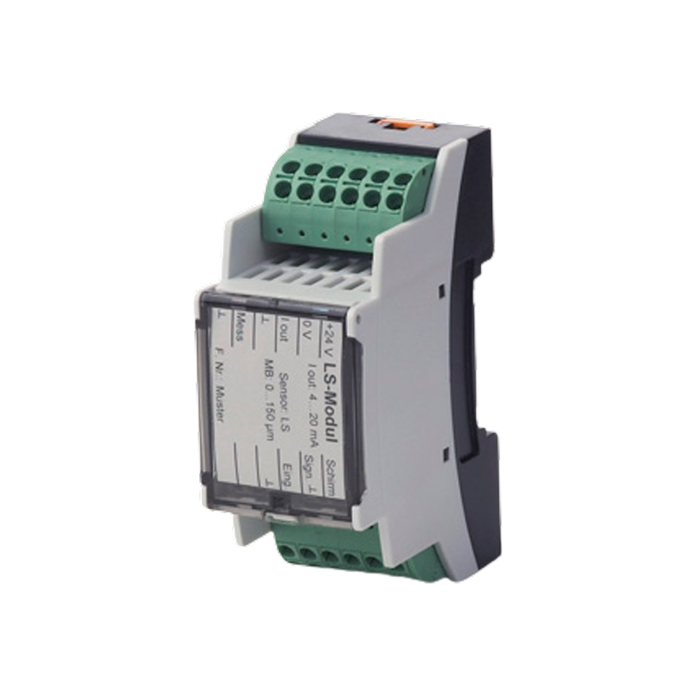
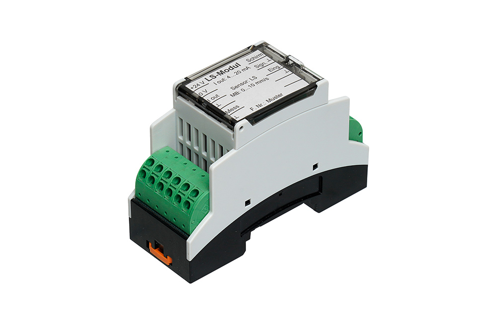
Analogue single-channel measuring amplifier / evaluation board for measuring absolute housing vibrations by means of electrodynamic / seismic sensors
- Compact top-hat rail module
- Peak value and rms value evaluation (0-P/P-P/RMS)
- Measuring range 10...100mV/mm/s at 10 ... 1000Hz
- Supply voltage 18...30 VDC
- Output signal 4...20 mA
- Decoupled raw signal output for verification
- Integrated sensor / self-monitoring
Technical data
| Measuring range | 10...100mV/mm/s at 10...1000Hz | ||||
| Suitable sensors / measuring chains | Seismic / Electrodynamic Vibration Sensors | ||||
| Type of processing | Peak value rectification / RMS value rectification | ||||
| Supply voltage | 18 ... 36 VDC | ||||
| Power consumption | max. 100 mA | ||||
| Sensor sensitivity adjustment | by means of a fixed resistor | ||||
| Measuring range adjustment | by means of a fixed resistor | ||||
| Tape fit adjustment | by means of a fixed resistor | ||||
| Default setting | MB: 0...20mm/s or 0...50µm / Iout 4...20mA at Vin 28,8mV/mm/s | ||||
| Measuring circuit monitoring | Power failure / signal error | ||||
| Output signal in case of error | 0mA / Green LED goes out | ||||
| Hold time error signal (0mA) | 20 Seconds | ||||
| Material module housing | Polycarbonat | ||||
| Protection class | IP 20 | ||||
| Permissible operating temperature | -20 ... +70 °C | ||||
| Connection according to UL standard | AWG/kcmil: 30-12 | ||||
| Clamps for wire cross-section | 0,2 to 1 mm2 | ||||
Do you have further technical questions about the product?
We will be happy to help you determine the order code and provide you with further specific information for your required product.
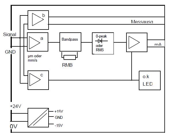
Circuit diagram and function
Signal conditioning
The output signal of the sensor is divided into three function paths at the signal input:- Signal conditioning
- Decoupling for the analysis output
- Measuring circuit monitoring
rectified in the peak value rectifier. The signal is converted into a standard current signal and output as a 4...20 mA signal.
At the test output, the sensor signal is available unfiltered and decoupled for measuring and analysis purposes.
The measuring circuit monitoring detects a sensor defect as well as a power failure. In the event of a fault, the Current output is switched to 0 mA and the green LED goes out.
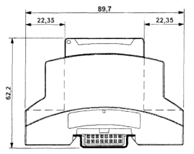
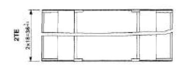
Dimensional drawings
Compact design
Housing dimensions approx. 90 x 62 x 2TE
