LVDT sensor EDT

with integrated electronics
  • Full (symmetric) LVDT configuration

  • Available strokes 50, 100 and 200 mm

  • Standard version:

    - Supply +10...+30 VDC
    - Output +2...+10 VDC, 4...20 mA, PWM

  • Mini version (20 mm shorter than standard):
    - Supply +5 VDC
    - Output +0,5...4,5 VDC or PWM

Important features

  • Nominal stroke: 15 mm up to 200 mm
  • Installation length: 180 mm to 360 mm
  • Case diameter: 3 mm
  • Operating temperature: 0 ... 70 °C
  • Protection class (DIN 40050): IP 64

Technical data

   
EDT 50
EDT 100
EDT 200
Nominal stroke mm ±25 ±50 ±100
Mechanical stroke mm 52 102 205
Dimension B, Mini- / Standard version mm 180 / 200 240 / 260 340 / 360
Dimension A, others optional* mm 57 102 200
Sensor weight (approx.) g 170 200 240

* Specify options on order

Equal product values

  EDT 50 ... 200
Body diameter D 12h9
Core diameter d (incl. PTFE coating)1) 3 (3,5) mm
Power supply UB Version /A: +15 ... +30 VDC (+10...+30 VDC bei RLast<200Ohm)
Versionen /V, /P: +10 ... +30 VDC
Versionen /VM, /PM: +5 ± 0,25 VDC
Output signal
(inner end position ... center position ... outer end position)
*) optional: inverted output signal
Version /A: 4 ... 12 ... 20 mA (with RLoad < 500 Ohm)
Version /V: +2 ... +6 ... +10 VDC
Version /P: PWM (TTL level) pulse-width 10 ... 50 ... 90 %
Version /VM: +0,5 ... +2,5 ... +4,5 VDC
Version /PM: PWM (TTL-level) pulse-width 10 ... 50 ... 90 %
Linearity  < ±0,5 % F.S.O.
Temperature coefficient of output signal < ±0,5 % / 10 K
Operating temperature* 0 °C ... +70 °C
Protection class (DIN 40050) IP 64
* Specify options on order
1) Core PTFE coating is provided for mechanical purposes (improved sliding) without influence on sensor electrical characteristics.
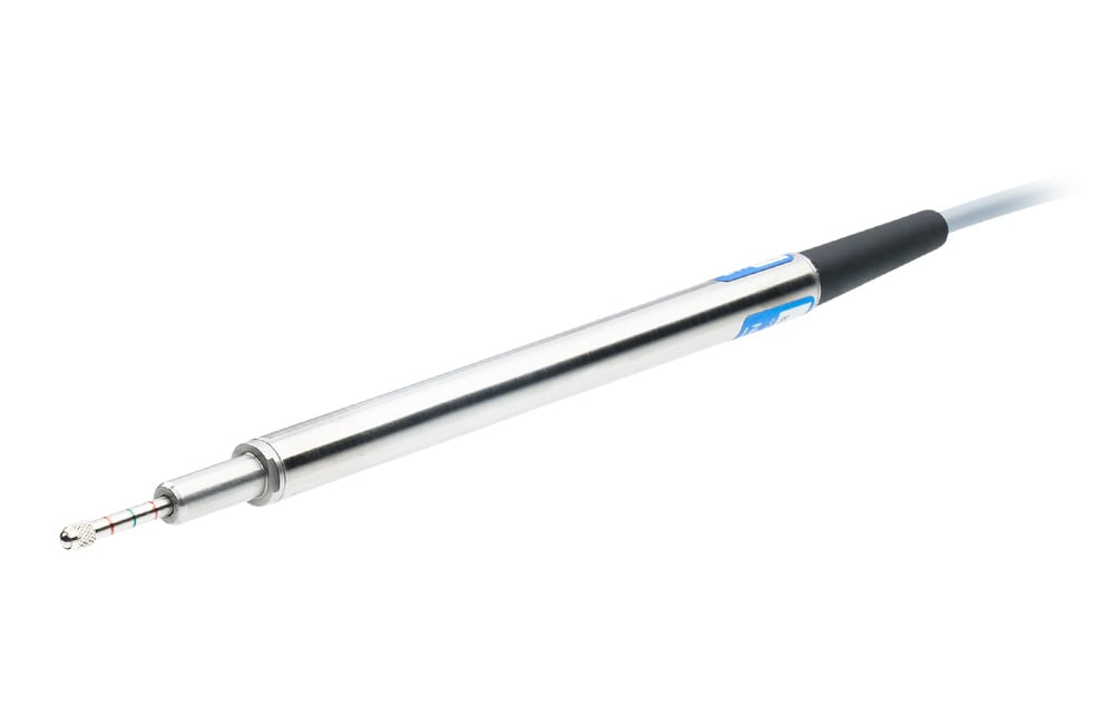
Model list

    Abbr. EDT
Stroke see technical data   50 ... 200
Connection Leads none (AWG 30)
Axial PE-cablel 1) K
Radial PE-cable 1) Q
Axial connector 1) 2) LX
Radial connector 1) 2) R
Linearity (FSO) 0,5 %  


Version /A /A  
Version /V /V  
Version /P /P  
Version /VM /VM  
Version /PM /PM  
Options
Inverted output signal (decreasing) /INV optional
PTFE cable /TF optional

1) Core channel not continuous
2) Mating connector supplied

Dimensional drawings / Connection variants

Leads ( )

dimensional-drawing-edt-leads

Axial cable (K)

dimensional-drawing-edt-axial-cable

Radial cable (Q)

dimensional-drawing-edt-radial-cable

Radial connector (R)

Total body length: Dimension B+5

**)  20x20

dimensional-drawing-edt-radial-connector

Axial connector (LX)

dimensional drawing edt axial connector

Electrical connection

connectors edd
connection edd


Leads ( ) Cable (K) / (Q) Connector (R) Connector (LX) Signal Comments
Red Red 1 1 UB (supply) >>> non-isolated potential !!!
for /A, /V, /P: reverse polarity protection
Für /VM, /PM: NO reverse polarity protection !!!
Black Black 2 2 COM Reference potential for supply and output
White (or yellow) White 3 3 Output /A, /V >>> Don't connect external voltage !!!
Blue Blue 4 4 Output /P, /VM, /PM >>> Don't connect external voltage !!!
-- Shielding 5 Cabinet Shielding  

Downloads

icon-pdf-blueProduct data sheet

Accessories

dlh main picture perspective

Accessory 1

View products

dlh main picture perspective

Accessory 2

View products

dlh main picture perspective

Accessory 3

View products