LVDT sensors
EDL / EDU
Very short LVDTs with integrated signal conditioner
- Fully symmetrical LVDT design, up to 75 % of the overall length can be used as measuring range
- EDL with Ø 12 mm for standard applications
- EDU with robust Ø 16 mm for rough use
- Standard version
• Supply +10...+30 VDC
• Output +2...+10 VDC, 4...20 mA, PWM - Miniature version (20 mm shorter)
• Supply +5 VDC
• Output +0,5...4,5 VDC or PWM
Important features
- Nominal stroke: 15 mm up to 1000 mm
- Installation length: 430 mm to 1470 mm
- Case diameter: 3 mm
- Carrier frequency: 5 kHz (option: 10 kHz)
- Operating temperature: 0 ... 70 °C
- Protection (DIN 40050): IP 64
Technical data
|
EDL 50
EDU 50 |
EDL 100
EDU 100 |
EDL 200
EDU 200 |
EDL 300
EDU 300 |
EDL 400
EDU 400 |
EDL 500
EDU 500 |
|
Nominal stroke | mm | ±25 | ±50 | ±100 | ±150 | ±200 | ±250 |
Mechanical stroke | mm | 55 | 105 | 210 | 320 | 420 | 520 |
Dimension A, other dimensions as option* | mm | 55 | 80 | 135 | 190 | 240 | 290 |
Installation length B, mini / standard version | mm | 130 / 150 | 190 / 210 | 290 / 310 | 400 / 420 | 510 / 530 | 630 / 650 |
* Specify options on order
EDL 50
|
EDL 100
|
EDL 200
|
EDL 300
|
EDL 400
|
EDL 500
|
||
Displacement transducer diameter | mm | 12 h9 | 12 h9 | 12 h9 | 12 h9 | 12 h9 | 12 h9 |
Core rod diameter / incl. Teflon coating |
mm | 3 / 3,6 | 3 / 3,6 | 3 / 3,6 | 3 / 3,6 | 3 / 3,6 | 3 / 3,6 |
Sensor weight (approx.) | g | 80 | 100 | 150 | 180 | 220 | 250 |
Core weight (approx.) | g | 7 | 10 | 15 | 20 | 26 | 32 |
EDU 50
|
EDU 100
|
EDU 200
|
EDU 300
|
EDU 400
|
EDU 500
|
||
Displacement transducer diameter | mm | 16 ±0,1 | 16 ±0,1 | 16 ±0,1 | 16 ±0,1 | 16 ±0,1 | 16 ±0,1 |
Core rod diameter / incl. Teflon coating |
mm | 5 / 5,6 | 5 / 5,6 | 5 / 5,6 | 5 / 5,6 | 5 / 5,6 | 5 / 5,6 |
Sensor weight (approx.) | g | 140 | 190 | 280 | 380 | 480 | 580 |
Core weight (approx.) | g | 20 | 28 | 45 | 60 | 78 | 94 |
* Specify options on order
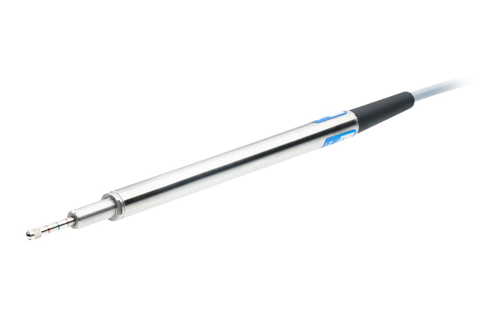
1) The Teflon coating of the core rod is only for mechanical sliding and has no influence on the electrical properties of the LVDT sensor.
Properties
EDL / EDU 50 ... 100 |
|||||||
Supply UB | Version /A: +15 ... +30 VDC (+10...+30 VDC at Rload < 200 Ohm) Versions /V, /P: +10 ... +30 VDC Versions /VM, /PM: +5 ± 0.25 VDC |
||||||
Output signal (inner end position ... middle position ... outer end position) Inverted output signal as an option* |
Version /A: 4 ... 12 ... 20 mA (at Rload < 500 Ohm) Version /V: +2 ... +6 ... +10 VDC Version /P: PWM (TTL level) with duty cycle 10 ... 50 ... 90 % Version /VM: +0.5 ... +2,5 ... +4.5 VDC Version /PM: PWM (TTL level) with duty cycle 10 ... 50 ... 90 % |
||||||
Linearity | < ±0,5 % F.S.O. | ||||||
Temperature coefficient of the output signal | < ±0,5 % / 10 K | ||||||
Operating temperature* | 0 °C ... +70 °C | ||||||
Protection class according to DIN 40050 | IP 64 |
* Specify options on order
Model list
Abbr. | EDL | EDU | ||
Measuring range | see technical data | 50 ... 500 | 50 ... 500 | |
Connection variant | Leads | none | (AWG 30) | (AWG 26) |
Axial PE cable1) | K | |||
Radial PE cable 1) | Q | |||
Axial connector 1) 2) | LX | |||
Radial connector 1) 2) | R | |||
Linearity (FSO) | 0,5 % | |||
Version /A | /A | |||
Version /V | /V | |||
Version /P | /P | |||
Version /VM | /VM | |||
Version /PM | /PM | |||
Options |
Output signal inverted (decreasing) | /INV | optional | optional |
Custom dimension A | /Axx | optional | optional | |
Core teflon coated | /KT | Serie | optional | |
Teflon cable | /TF | optional | optional |
1) Core channel not continuous
2) Mating connector supplied
Do you have further technical questions about the product?
We will be happy to help you determine the order code and provide you with further specific information for your required product.
Dimensional drawings / Connection variants
Leads ( )

Axial cable connection (K)

Radial cable connection (Q)
Transducer length = Dimension B+5
*) for EDL: 15x15; for EDU: 20x20

Radial connector (R)
Transducer length = Dimension B+5
**) for version R: 20x20

Axial connector (LX)

Electrical connection


Leads ( ) | Cable (K) / (Q) | Connector (R) | Connector (LX) | Signal | Note |
Red | Red | 1 | 1 | UB (Supply) | >>> Not electrically isolated !!! For /A, /V, /P: polarity reversal protection For /VM, /PM: NOT reverse polarity protected !!! |
Black | Black | 2 | 2 | COM | Reference potential for supply and output |
White (or yellow) | White | 3 | 3 | Output /A, /V | >>> Do not apply ext. voltage !!! |
Blue | Blue | 4 | 4 | Output /P, /VM, /PM | >>> Do not apply ext. voltage !!! |
-- | Shield | 5 | Casing | Shielding |